Motors and Arduino for Robotics
Week 2 • CMPSC 304 Robotic Agents
Press Space or → to advance
Today's Agenda
- Arduino Uno basics and power flow
- Digital vs. Analog signals
- Pulse Width Modulation (PWM)
- Battery voltage calculations
- Why we need motor drivers
- DC motors for Project 1
- Motor types overview
Arduino Uno Overview
USB Connection
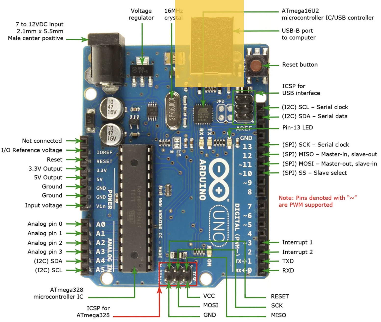
- Used to upload code to the Arduino microcontroller
- Powers the Arduino during programming
- Enables serial communication for debugging
Digital Input/Output Pins (0-13)
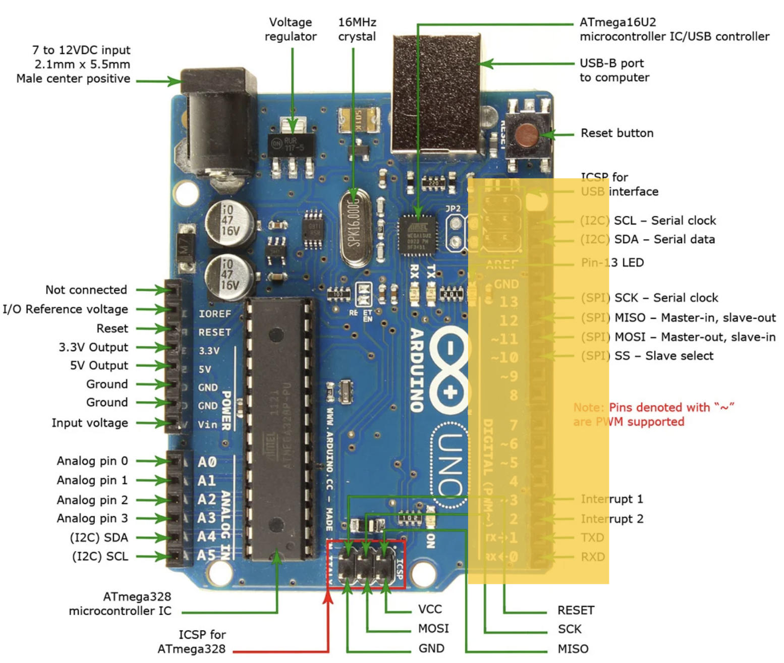
- Pins can be HIGH (5V) or LOW (0V)
- Outputs: Turn on an LED every 10 seconds to make it blink
- Inputs: Read sensor data (e.g., is surface wet or dry?)
- Pins with ~ symbol: Support PWM (Pulse Width Modulation)
- PWM pins: 3, 5, 6, 9, 10, 11
Analog Input Pins (A0-A5)
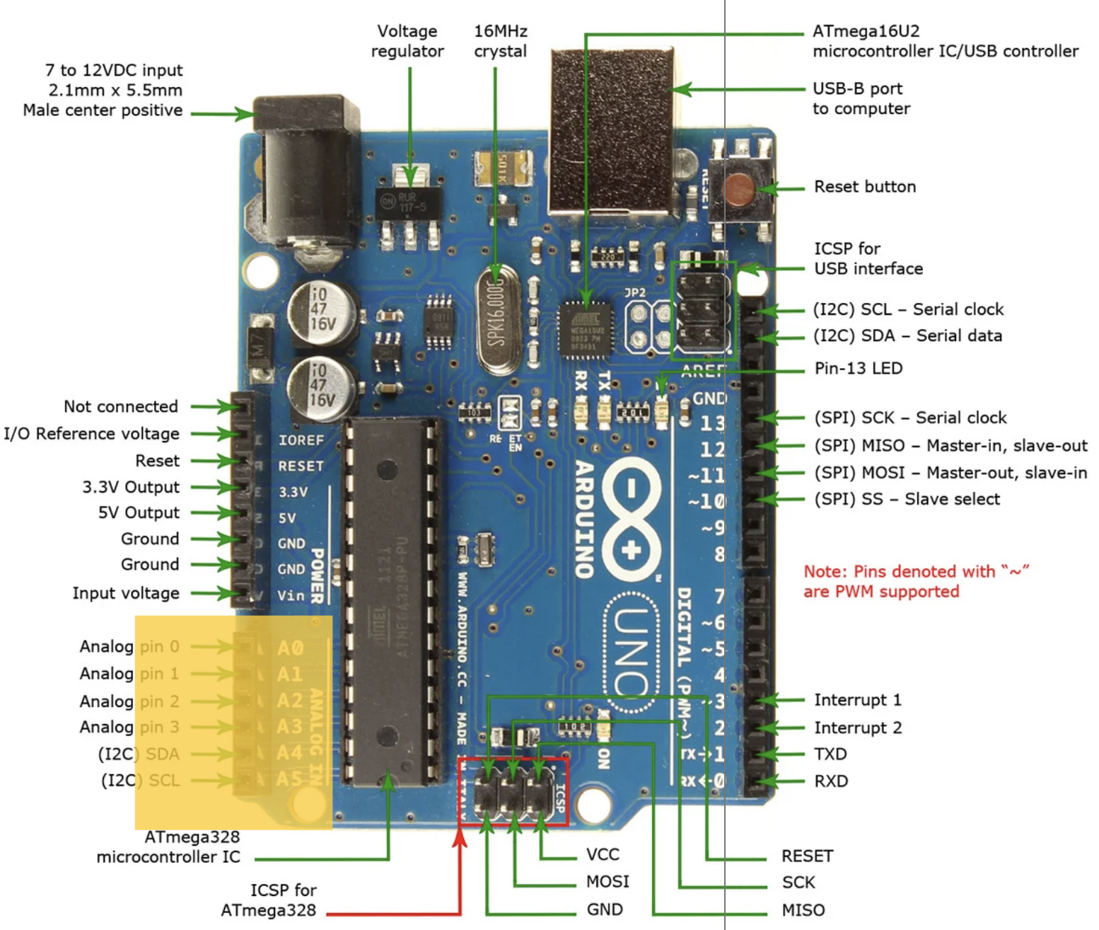
- Can read a range of values (0-1023)
- Perfect for sensors with continuous output
- Examples: Distance sensors, light sensors, temperature sensors, potentiometers
Power and Ground Connections
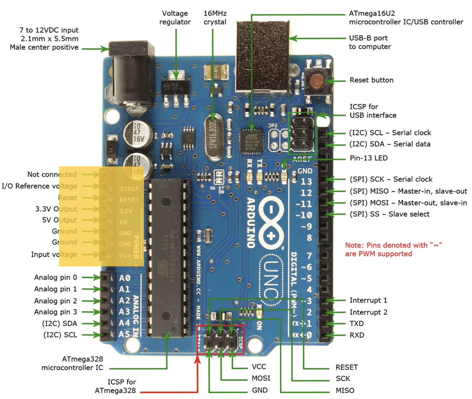
- 5V pin: Provides 5 volts (HIGH)
- 3.3V pin: Provides 3.3 volts (for sensitive components)
- GND pins: Ground/reference voltage (LOW, 0V)
- Vin: Input voltage (7-12V recommended)
- Circuits flow from GND to HIGH to complete the circuit
Digital vs. Analog Signals
Digital
HIGH (5V) or LOW (0V)
- ON or OFF (like light switch)
- Pins 0-13
digitalWrite(13, HIGH)
Analog
Range: 0V to 5V
- Continuous values (like dimmer)
- Reads 0-1023 (Pins A0-A5)
analogRead(A0)
Pulse Width Modulation (PWM)
Problem: Arduino digital pins are only HIGH or LOW
Question: How do we get "in-between" voltages?
Answer: PWM = rapidly switching between HIGH and LOW!
How PWM Works
Rapidly switch HIGH/LOW → Motor sees average voltage
Duty Cycle Examples:
- 25% duty cycle: 0.25 × 5V = 1.25V
- 50% duty cycle: 0.50 × 5V = 2.5V
- 75% duty cycle: 0.75 × 5V = 3.75V
- 100% duty cycle: 1.00 × 5V = 5V
PWM on Arduino
PWM pins (marked with ~): 3, 5, 6, 9, 10, 11
analogWrite(9, 0);    // 0% duty cycle = 0V (motor stopped)
analogWrite(9, 64);   // 25% duty cycle = 1.25V (slow)
analogWrite(9, 128);  // 50% duty cycle = 2.5V (medium)
analogWrite(9, 191);  // 75% duty cycle = 3.75V (fast)
analogWrite(9, 255);  // 100% duty cycle = 5V (full speed)
PWM values: 0-255 (not 0-1023 like analogRead!)
Why PWM for Motors?
- ✓ Efficient: Minimal heat
- ✓ Simple: No voltage regulation
- ✓ Precise: 256 speed levels (0-255)
- ✓ Digital pins: No analog output needed
Motor inertia smooths pulses → steady voltage
Battery Voltage: 4 AA Batteries
Question: Yellow DC motor kit comes with 4 AA battery holder. What voltage is this?
Answer: 6 volts
How Do We Know?
AA battery = 1.5V (1.2V rechargeable)
Series connection: Voltages ADD
4 × 1.5V = 6V total
Series vs. Parallel Batteries
Series: Voltages ADD
- End-to-end: 1.5V + 1.5V + 1.5V + 1.5V = 6V
- Capacity: Same (2000 mAh)
Parallel: Capacity ADDS
- Side-by-side: Voltage stays 1.5V
- Capacity: 4 × 2000 = 8000 mAh
Battery Voltage Over Time
| Battery State | Alkaline AA | Your 4× AA Pack |
|---|---|---|
| Fresh | 1.5V - 1.6V | 6.0V - 6.4V |
| Nominal | 1.5V | 6.0V |
| 50% used | 1.3V | 5.2V |
| Depleted | 1.0V | 4.0V |
⚠️ Motors slow down as batteries drain!
Why We Need Motor Drivers
Critical Problem: Arduino pins cannot directly power motors!
Arduino Pin Limitations
Arduino Pin
- Max: 20-40 mA
DC Motor
- Needs: 150-300 mA
- Stall: 1-2 A
Motor draws 10× more than Arduino!
What Happens Without a Driver?
✗ Direct connection
- Pin tries to supply 150+ mA
- Rated for only 20-40 mA
- → Damaged Arduino!
✗ Motor stalls
- Current spikes to 1-2 A
- → Permanent damage!
Motor Driver to the Rescue!
Power bridge controlled by low-current signals
- Arduino: LOW current control (< 20 mA)
- Driver: HIGH current from battery (1-2 A)
- Motor powered by battery, not Arduino
- Arduino stays safe!
Motor Driver Functions
- ✓ Current amplification
- ✓ Direction control (H-bridge)
- ✓ Speed control (PWM)
- ✓ Protection (overcurrent)
- ✓ Isolation (reduces noise)
Breadboard Basics
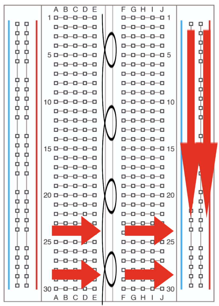
- Solderless prototyping
- Horizontal rows: Connected
- Vertical rails: Power/GND
- Red: + voltage (5V)
- Blue/Black: Ground (GND)
DC Motors for Project 1
Yellow Geared DC Motors
- Type: Brushed DC with gears
- Voltage range: 3-6V (motor's operating range)
- Your power: 4× AA = 6V (at upper limit)
- Application: Wheeled robot
- Features:
- Gears reduce speed, increase torque
- Two-wire control (polarity = direction)
- Current: 150-300 mA (1-2A stall)
Motor Driver: L298N
- Controls: Speed & direction
- H-Bridge: Bidirectional control
- Specs:
- 2 motors, up to 2A each
- Logic: 5V, Motor: 5-35V
- Pins:
- IN1/IN2: Motor A direction
- IN3/IN4: Motor B direction
- ENA/ENB: Speed (PWM)
Alternative Motor Drivers
TB6612FNG
- More efficient
- Up to 1.2A/channel
WWZMDiB
- Compact design
- Space-saving
Any driver works for Project 1!
Next Steps for Project 1
- Mechanical build, wiring, power
- Install fresh batteries (6V)
- Test motors before mounting
- Verify driver connections
- Start with low PWM (50-100)
- Document your wiring
Types of Electric Motors
- Brushed DC Motors (what you're using)
- Brushless DC Motors
- Stepper Motors
- Servo Motors
Brushed DC Motors
Pros
- Simple control
- Inexpensive
- Widely available
Cons
- Brush wear
- Lower efficiency
- Needs maintenance
Brushless DC Motors
Pros
- Higher efficiency
- Longer lifespan
- More torque/weight
Cons
- Needs ESC
- More expensive
- Complex control
Use: Drones, RC cars
Stepper Motors
Pros
- Precise positioning
- Holds position
- No encoder needed
Cons
- Lower speed
- Can lose steps
- Needs driver
Use: 3D printers, CNC
Servo Motors
Types
- Standard: 0-180°
- Continuous: 360° speed control
- Digital: Faster, stronger
Built-in control, easy to use, compact
Use: RC vehicles, arms
Other Actuation Technologies
Hydraulic
- Pressurized liquid
- Very high force
- Large, expensive
- Use: Construction
Pneumatic
- Compressed air
- Lightweight, safe
- Lower force
- Use: Soft robotics
Safety Considerations
Active
- Torque limiting
- Collision detection
- Emergency stop
Passive
- Mechanical limits
- Compliant materials
- Fail-safe brakes
- Fuses/breakers
Key Takeaways
- Digital = ON/OFF; Analog = range; PWM = fast switching
- 4× AA = 6V (series)
- Arduino pins cannot power motors directly
- Motor drivers amplify & protect
- PWM controls speed (0-255)
- Motor types: trade-offs in precision, force, speed, cost
Questions?